This is the Minneapolis - St. Paul section of
The Broadcast Archive
Maintained by:
Barry Mishkind - The Eclectic Engineer
Last Update 5/22/03
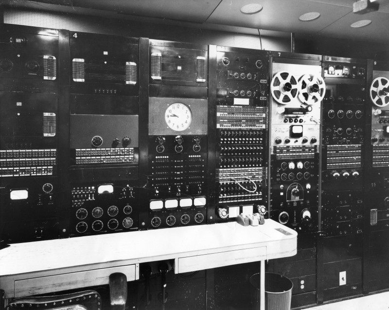
The Master Control Rack racks in the 1960 era.
| Comments by Mark Durenberger 6/7/03
My guess is that the WCCO Master Control ("M-C") photo was
taken late 50's or early 60's. The Ampex 350's would set the date; they
were probably new when this photo was shot; the metal reels in use were
early versions. (A few years later, WCCO engineers milled the tape reel
hubs a few millimeters narrower, to eliminate tape wrap.) The first few racks also contained several bays of RCA tube
amplifiers (these were the guys with the chrome-plated transformers).
These amplifiers supported the various passive studio-based mixers. Note
that the amplifier bay swing-down doors are made by RCA
but have tiny
"CBS" labels. Those tube-amplifier bays were replaced in the
mid 60's with RCA "BA-series" solid-state amplifiers; that upgrade
meant less down-time for tube-testing
but it was the first step toward
adding serious grunge to the audio. Beneath the first three lever keys (the mikes) were on-off switches, overriding the booth mike controls. Urban Legend: These switches were known as "Union Controls" or "Defense Overrides". Engineers could shut off mikes if need be .the concern may have been guarding against a takeover of the studios by hostile entities. End of Urban Legend. Why not just turn down the faders? Astute viewers will note the difference between the M-C photo and a latter-day view of the Studio 5 mixer. A dedicated fader replaced "Master" with an input from the State Fair, where WCCO had a seasonal studio. The "Monitor" fader was replaced by a white "telephone bus" sometime in the late 1960s. This phone bus was pretty unique for its (pre-hybrid) time; it allowed entry to the phone system from several sub-consoles. This meant you could mix a show from one studio with programming from another, adding the phone, without further assignments or patching. Rack 5 (with the clock) held the output distribution
"Pre-selector" and controls for the three main monitors in the
control room. The monitors were physically separated across the room so
as to be available for either foreground or background monitoring,
depending on the duties of the moment. "Channel 1" from the Pre-selector was the feed to the transmitters. During the Conelrad/Civil Defense days there was an interrupt amplifier located in the newsroom; a newsman could lift a mike off its pedestal and interrupt Channel 1, going directly to air. Note the absence of any audio processing. Programming was fed
"barefoot" to the transmitter where it was protected by
General-Electric BA3 and BA-5 limiters. The only other audio
modification was a 50 hz. high-pass filter at the transmitter that kept
DC clicks and thumps from dumping the Dohertys. Eventually a Gates
"Level-Devil" was tried (ouch!) and that was replaced by the
venerable CBS Audimax. Using three-way lever keys, 12 telco trunks could be fed "program cue" or used as the inbound channels. Associated keys allowed you to group remote lines so that for example you could associate a "cue" line with an inbound program line as well as (ancient history) a "go-ahead" dry pair this from the days when a telegraph key would be used to transmit the famous go-ahead "K". The selected inbound loop(s) could be equalized and assigned to either the "X" bus or the "Y" bus. The "X" Bus appeared on the Green fader on Studio 5; the "Y" Bus was meant for off-air pre-alignment but could also be patched to air. 12 trunks was more than enough for us to handle; the phone company test board had dozens of others ready to be "funneled down" to these 12. At the bottom of rack 6 is a row of telephone trunk keys complete with ring-down arrangements. Push a key UP to grab one of the handsets beneath the table; pull down to grab the other. "Ring-down" push-buttons allowed you to instantly connect to the local telco test board. It wasnt unusual during a remote set-up to have a phone in each ear. (And I remember those were HEAVY handsets!). Also...speaking of phone loops...you can't see the several
"monitor" amplifiers that drove telco dry pairs to various
agency and sponsors offices around town. These offices had a
monitor amp/speaker, sometimes used not for off-air listening but to
'preview' (and approve?) a show originating in one of the
studios.
The gear in the top half of rack 8 is a mystery to me. But directly between the Ampex electronics can be seen the panel with tape-input selectors, "on-air" "B-Keys" and separate cue/monitor controls. At the very bottom of rack 8 is a typical "A/B" switch that transferred the racks DC control voltage from 'regular' to 'emergency.' (I have to tell a short story: That switch got us in serious trouble one night in 1967 when we lost power during a tornado. The janitor had bumped a similar switch under rack 3; controlling mike relays. Because it was under the table we didnt see that it was in the wrong position. When the storm came through and the power barfed, the emergency power came up fine; studio lights worked; amplifiers and VU meters were lit up. But we couldn't get the mikes on! We got back on by scrambling a Collins remote amp, patching directly to the transmitter feed and handing a mike to the talent who worked from M-C for the duration. I had been there three months and received ten years worth of experience that night.) The bottom of Rack 8 contains what looks like the remains of the
power supply, audio-assigns and tube analyzer for the original
disc-cutting equipment. There were two more racks on that end (10 and
11). They contained monitor amplifiers and a third Ampex 350. (Another
story: Freddie Hermann was an engineer about 5 feet long, whose last
duty of the day was to go to rack 11 to record the 5PM CBS news for
playback at 5:10. Freddie needed a step-stool to reach the Ampex. Hed
climb aboard, set the recorder in motion and leave. The only problem is,
hed also leave the cue speaker on (wide open because he was hard of
hearing). No problem; there was nothing on the net at that point. 5PM
was a VERY busy switch time; straight up, just as you were swinging into
the major local newscast, the CBS news would come booming out of the cue
speaker Freddie had left wide-open. Youd dive for the rack to dump
the cue amp
.usually stumbling over Freddies step-stool in the
process. Each of the three turntables (and, in fact, each of the dozen or so
tape machines around the place) had its own cue amp, volume control and
speaker. Again...the spatial separation of the speakers and their
location next to the appropriate machine helped the engineers when it
got very busy in that room. Studios that worked in conjunction with M-Cs "Studio 5"
were: "Studio 1" (decommissioned by this time); "Studio
2", the audience-participation studio, "Studio 3", the
edit/production studio and "Studio 4", primarily a recording
control room. 1 and 2 used passive mixers and 3 also had an active
console (RCA 76B-2). 4 had a Collins 212. Driving a station with a 55% share of the audience, we did a lot of
on-air engineering by the seat of our pants. But we had the tools to do
it. Mark Durenberger
|