WLW was the pride of Powel Crosley's empire. Constructed to sell the radios his factory produced, WLW became the most powerful AM broadcast station ever licensed for use in the US. Over the years, WLW grew from 20 watts to 500,000 watts, eventually settling down to a "mere" 50,000 watts.
Developed out of the experimental station 8XAA, WLW received License #312 from the Department of Commerce on March 2, 1922. An early adopter of the vertical antenna structure for transmission, WLW got its first one when it purchased WMH, whose antenna had a wine bottle for an insulator!
In order to sell more and cheaper radios, Crosley understood he had to have more and more powerful transmitters. So, as quickly as the technology and the government would allow, WLW increased its transmitter power to 500, 1000, 5000, and in 1928, 50,000 watts, installing a Western Electric Model.
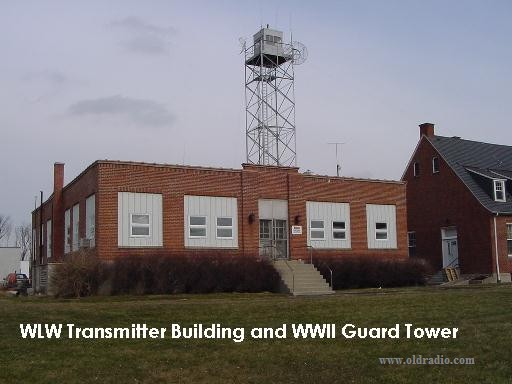
The transmitter site was located in Mason, OH, to the NE of the city of Cincinnati. This permitted the station to have sufficient land and electrical service, something that would be of great importance in a few years.
Of course, during wartime, this site was considered an enemy target, so there were appropriate guards (and a guard tower) to prevent unauthorized entry to the transmitter building or the area around the tower.
The house on the right was for the staff, and was occupied by Paul Jellison and his family.
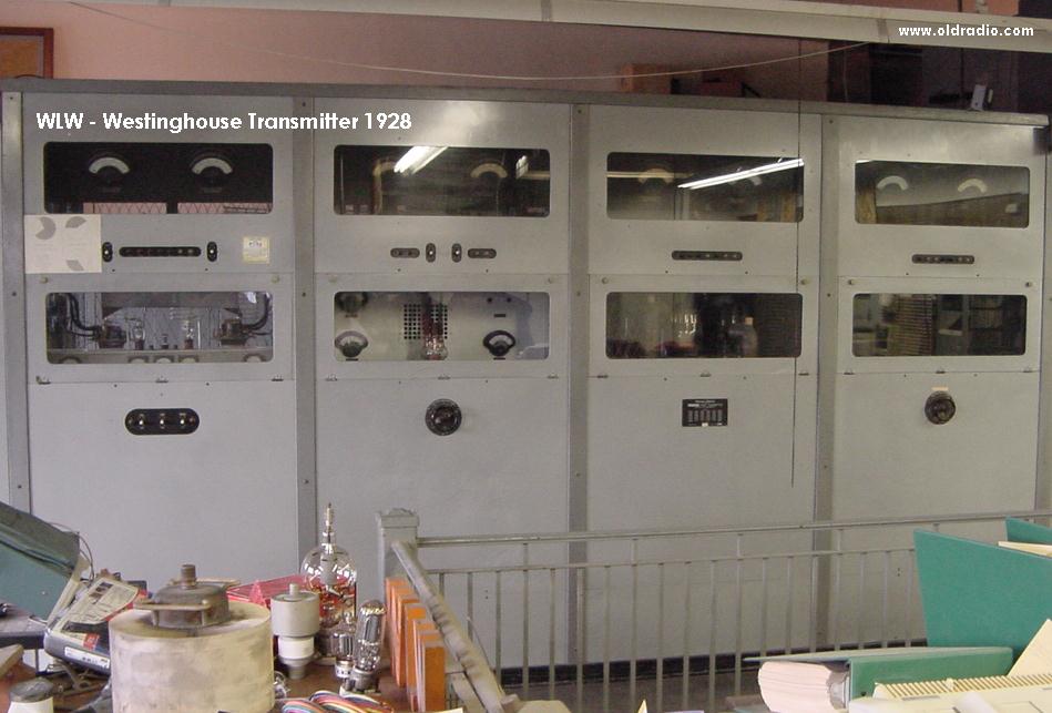
The first 50 kW transmitter at WLW (and among the first anywhere) - a Western Electric D-94955, Serial #105.
This 70+ year old transmitter was still operable until recently and actually was put back on the air by the current WLW Chief Engineer, Paul Jellison, to commemorate New Year's Eve 1999 into 2000.
Of course, the transmitter that everyone wants to talk about is the 500,000 watt monster, built by RCA.
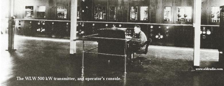
It took as many as 17 operators at a time (from
a staff of 63), to run it,
not to mention an air staff of 190 full and part time
performers.
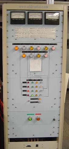
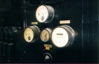
Here is a close up of one set of the meters seen on the front of the transmitter.
It is interesting to note that as soon as this
transmitter was turned on, there were complaints
that it was interfering with
station CBL (690) in Canada, and a directional system
was produced limiting
radiation in the minima to "only" 50,000 watts.
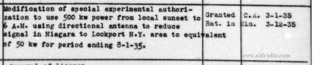
Notation on FCC license card, showing WLW's directional operation at night
 |
 |
|
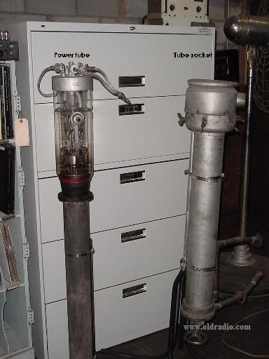
| Everything about this transmitter was huge. The tube assembly was as tall as a person (over five feet). The UV-862 tubes (all 20 of them - 8 modulators and 12 PA tubes!) went into sockets allowing water from the pond out front to circulate for cooling. The filaments alone took 33 volts and 207 Amps of current. (Other tubes in use included the UV-211, UV-848, UV-849, and UV-872.) |
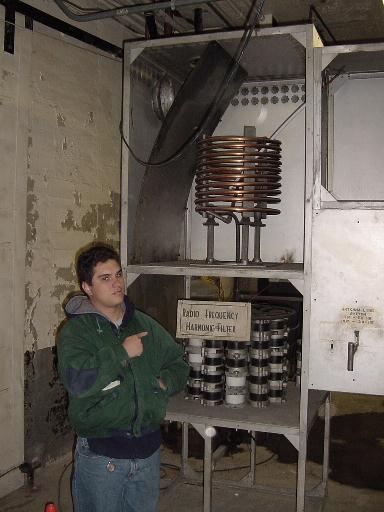
The Harmonic Filter had just a couple of caps in it! |
|
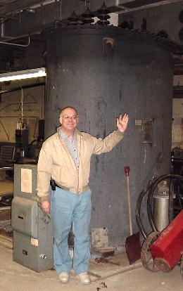
The Modulation transformers were each twice as high as a man, and weigh 35,700 pounds each, including 725 gallons of oil. The other statistics are equally amazing:
Many more tech stats were in the October 1934 IRE technical paper: The WLW 500-kilowatt Broadcast Transmitter Two 33 kV power lines came to the transmitter building, 2300 VAC entered the building. Amazingly, with all that power, the calculation in 1934 was that it would cost $23.00 per hour to run the transmitter. (The use of Class B high level modulation saved $25,000 annually in electricity.) |
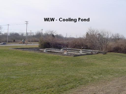
A 75 foot square pond held the water used to
cool the transmitter,
which needed something like 10,000 gallons of cool water a minute.
After the FCC was successfully lobbied to
refuse an extension for the 500 kW operation,
WLW returned to "only" 50,000 Watts on March 1, 1939.
 |
|
|
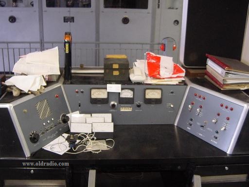
Original Control Desk for the WLW transmitters |
RF Control Switch |
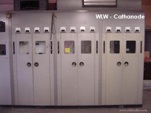
In the 1950s, the manufacturing arm of Crosley (now renamed AVCO), produced an interesting model. Designed by the VP of engineering and WLW Chief Engineer, R. James Rockwell, the AVCO Model 7 was said to be a very clean sounding transmitter. The Rockwell Cathanode used a modulation technique which produced a frequency range of from below 20 Hz to above 20 kHz with less than 1% distortion. Quite an achievement. It was an expensive transmitter to run, however, and is no longer maintained.
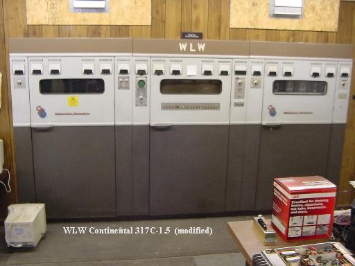
In 1975, WLW installed a Continental Electronics 317C1 transmitter.
In the 1990s, the solid state transmitters took over. The Harris DX-50 (1990) and 3DX-50 (1997)
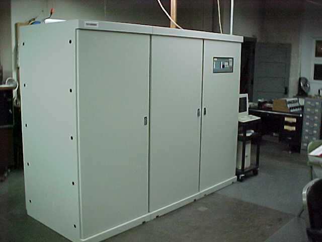
Paul Jellison notes that this was Serial #1 of
the 3DX-50 series. Largely due to the
"special" nature of this transmitter as essentially a prototype, it
was returned to
Harris, and daily operation returned to the DX-50 in 2004. A production model of
the 3DX-50
was installed shortly thereafter and continues to be the Main in 2009.
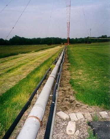
Next, the signal goes to the tower via the transmission line and the tower base.
|
|
The nine inch transmission
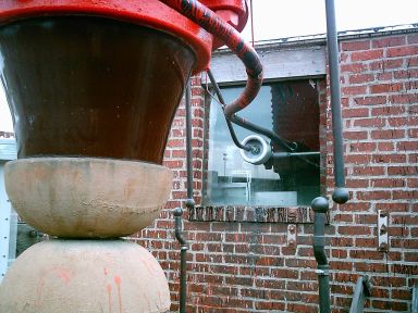
line carries the power out to the tower. At the tower, the base is
supported by the original Lapp insulator set.
Each section of the insulator is almost four feet tall and wide. Each half weighs a lot, all by itself, and then the tower weight is added to it! |
|
|
|
Of course, another remarkable part of WLW,
certainly the most visible
to the public, is the 739-foot tall Blaw-Knox tower:
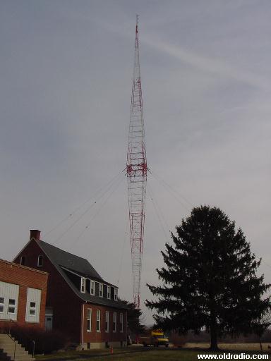
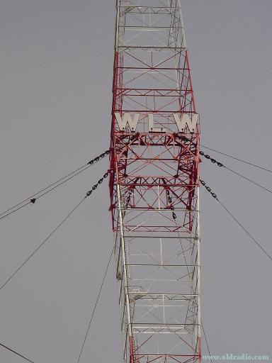
WLW's 739-foot, 200 ton tower was constructed from two Blaw-Knox self supporting antennas.
Up until this time, most stations were using horizontal antennas
held between two towers. WSM, down in Nashville, had just installed one, and the
crew proceeded to Cincinnati to build this one. The unique silhouette of
the antenna has been wrongly attributed to a need to handle the high current. It
was actually just coincidental, and in fact, George Brown pointed out the thick
middle would slow the radio waves a bit and change its radiation characteristics
in unwanted ways. In fact, due to skywave problems, the antenna had to be
shortened from the original 878 feet to 808 feet. WLW's 831 foot tower was
reduced to 739 feet.
Its reach was awesome. It was truly "The Nation's Station."
And there never has been another like it in the USA.
By 1939, there were political pressures to stop WLW's superpower. Whether it was attributed to WWII or to political intrigue by WLW's competitors, on March 1, 1939, WLW returned to radiating "only" 50 kW aside from some special broadcasts, on behalf of the US government, to send a message to Germany.
In fact, during the late 1930s and 1940s, more than 15 stations filed applications with the FCC for power levels in excess of the "normal" 50,000 watt level. Another round of applications accompanied a "Clear Channel Proceeding" in the 1960s. Yet, no authorizations were granted and today the maximum power on AM remains 50 kW.
Nevertheless, for almost five years, WLW fed an astonishing amount of power and talent to its tower. The cheap Harko and its relatives and cousins proliferated around the country, and radio became truly a "mass" medium.
Why was it that WLW alone achieved the "superpower" status among radio stations?
The answer lies in the form of a very special man: Powell Crosley.
My sincere thanks to Paul Jellison for his kind help in building this page.
Copyright 1995, 2003, 2004 Barry Mishkind. Please respect this and do not reproduce without permission.