 |
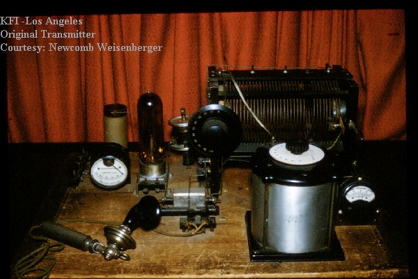
Earl C. Anthony's first transmitter - true "breadboard" construction. 1922 |
Here are some images and recollections from the folks who worked at KFI, the 50 kW flamethrower in LA.
|
Earl C. Anthony's first transmitter - true "breadboard" construction. 1922 |
|
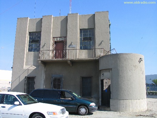
The original site of KFI ... |
|
|
In 1931, KFI installed a 50,000 watt transmitter in
Buena Park |
|
 |
|
|
The Buena Park facility |
|
 |
|
|
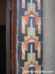
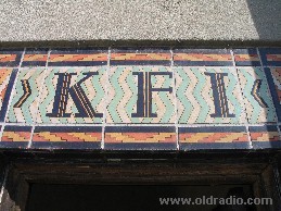
Over the door, the KFI call is shown in tiles. On
the door frame, you can |
|
|
|
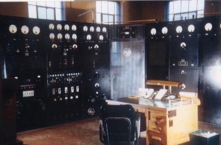
This is the original KFI 50 kW transmitter, an RCA 50B
Installed in 1931, it served as the main until a Continental 317B was installed in 1959. |
| Newcomb Weisenberger compares this with
the modern Harris solid state 50: "From my first visit to the
Harris transmitter, I think that it is noticeably safer that the RCA
50B.
"Both transmitters carry control and supply voltages. Unless the 250V DC is more damaging to the body than about that much AC those would seem to be equally dangerous. However, the old tube transmitter has, in addition, a secondary hazard in its plate supply, circuitry , switching, metering , sockets and contactors. "The 17,000-VDC plate supply, alone, employed a HV vault twice the size of the Harris transmitter with air insulated conductors, exposed bolt-on connections and an open filter bank of ganged capacitors. The HV full wave three phase MV rectifier assembly was as dangerous as the transmitter it fed. "I think that operating under such high tension, insulators, transformers, capacitors, coils etc are more apt to fail. That there also would be more sustained arc overs than if operating on a few hundred volts. "The final metering would not need to be double insulated as in the 50B. I think one would be more apt to survive an accidental contact with 250V than a brush with 17 kV. Given the resistance of the body in this instance. Less maintenance is required, for the Harris, the installation is safer. There is less exposure to danger. The point being that the more times you visit a dangerous place, the more ones safety is challenged. The use of 100% standby transmitters is a move to safety. Having
removed the added danger of a hurried repair with off air time a factor. |
|||
|
|
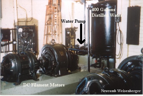
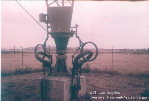
This picture shows the Filament Generator for the KFI transmitter.Using an AC generator to provide the DC current for the tubes, the picture also shows the distilled water tank and pump for cooling the tubes. | ||
| Newcomb adds: "KFI didn't have a formal safety program that
long ago. New men were 'broken in" by the men they were replacing.
They were trained one on one. We had two men on a shift and three on
maintenance. We watched over each other.
"The 50B was interlocked with the final filament voltage. The low voltage interlocks proved to be fail safe; i.e. all contacts had to be really clean and secure to close the circuit. A "Danger Man Working" sign was hung on the main switch while in the open position. There was a near accident: the vault was not interlocked but was secured by a heavy chain and padlock. It took deliberate action to go inside. A vacation relief man, being trained, closed this switch while the engineer was entering the vault on the first floor. When the vault door was opened, he could hear the H.V. corona discharging over the filter bank! "We made it a practice, whether or not it was necessary, to inform each other where we were at all times, day or night. This is a very important safety measure. When a man was sent to the tuning house, he reported by telephone. Again the house was locked and within a closed fence and locked gate. Carrier power was not applied without making telephone contact first, as once within the fence, there was no protection from the tower. "When off the air for maintenance we made it a practice to ground the tower with a shorting switch before cleaning the base insulator. Brush discharge often caused powerful arcs across the protective horn gaps. "The old transmitters also used open framed rotating motors, generators and water pumps. This too is a safety issue, mechanical and electrical. The bias machines were 1,000 volts. ( we checked the bearings every two hours, cleaned the contacts and pushed down the brushes as they wore away.) We used commutating cleaning sticks on the exciters for the huge 50/60 cycle changer. "The safety practices were those used with all moving machinery. No loose hair or clothing, secure footing, good lighting, safety glasses and attention to the task. By and large these safety practices were in force, but not forced. Not part of the transmitter safety but part of the engineers' safety, our machine shop with its power grinders, milling and drilling machines , compressor and lathe required good safety practices too. "To my knowledge, no KFI Engineer has had a serious work related accident."
|
|||
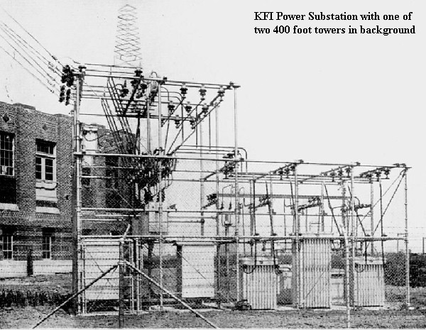 |
To feed the new 50 kW transmitter (the first west of Texas), a power substation was installed. In the background, you can see one of the two 400 foot towers used to hold the KFI antenna. | ||
|
|
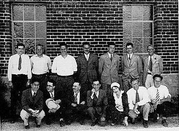
The KFI engineering staff, who built the new facilities. | ||
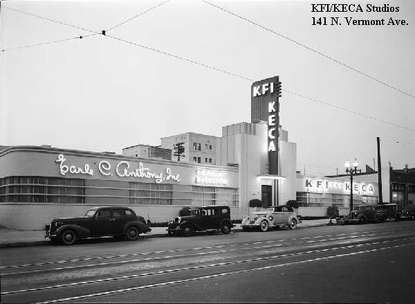 |
From the downtown car dealership, the studios were moved
in December 1939 to 141 N. Vermont Avenue.
This picture was taken after Anthony purchased KEHE and renamed it KECA (it is now KABC). |
||
| Newcomb Weisenberger comments: "At one time (after 1947) KFI considered Catalina Island as a transmitter site, for that reason. I was at BP then. We engineers were thinking about Island duty - the good and the bad." | |||
 |
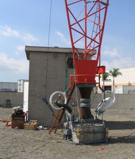
KFI Tower Base in La Mirada, California
750 feet tall, with the additional pressure from the guy wires, the tower may exert approximately 800 tons of pressure on the relatively small location where the tower sits on the insulator. Electrically the tower is 175 degrees (just under a half wavelength) tall. Note: Base insulators are only 4 inches thick. They are stronger because of the curve and being hollow! |
||
| Peter Haas notes: The tower was 175.7
degrees, just slightly above minimum conforming efficiency for its class
(374.98 mV/m/kW at 1 km vs. the 362.10 mV/m/kW at 1 km minimum).
The auxiliary antenna is about 46 degrees tall, a guess would put radiation at about 220 mV/m/kW at 1 km, which is only 36 percent as efficient as the minimum. All that means with 50 kW into its old stick, KFI was getting about 53.3 kW out, effectively. And with 25 kW into its auxiliary stick, KFI is getting about 9.2 kW out, effectively. |
|||
|
|
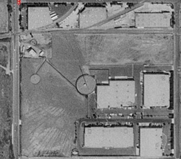
When KFI's La Mirada plant was built, there
was a lot more open space than there is today.
This picture was taken in 1994, after construction had started to "hem in" the tower. |
||
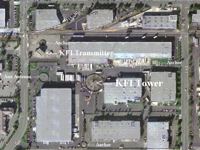 |
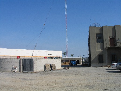
KFI Site -2004
You can see how the local business district is built up right around the tower. .... |
||
|
|
The KFI base as it appeared in spring 2004. | ||
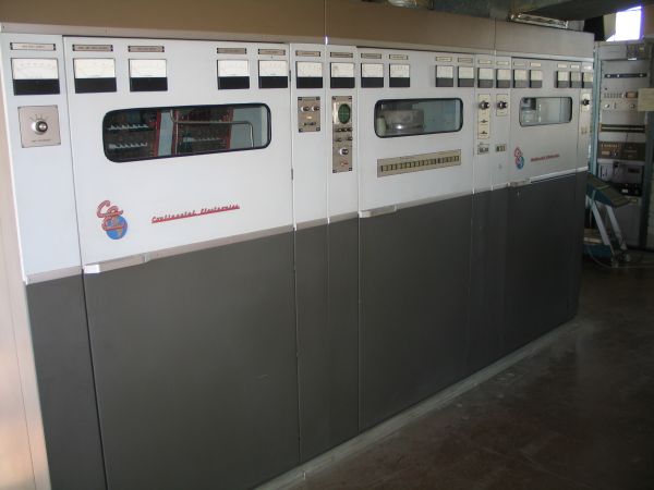
| A Continental 317-B was installed in 1959. (no picture currently available) and was the main until the 317-C1 was installed in tha late 1970s. The 317-C1 has been modified over the years to update it. | |||
|
|
A modified Continental 317-C1 was installed in the late
1970s.
This permitted the long running, RCA 50B (modified into a 50C) to be finally retired. |
||
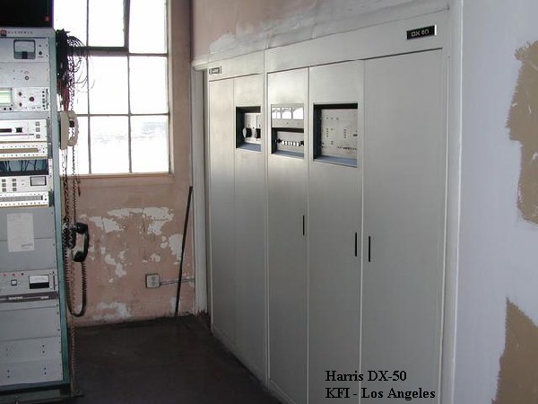 |
KFI Main Transmitter
Harris DX-50, installed in 1992. |
||
| In March, 2004, KFI changed out the guy wires after 57
years of operation.
|
 |
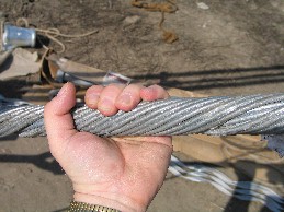 |
<=== The new guy wires are over an inch in diameter.
===> |
 |
| On the morning of Sunday, December 19, 2004, a private pilot
trying to land at the local airport hit the
KFI tower - destroying it - and killing the pilot and his wife.
Pictures of the disaster are located here. |
|
| Interesting places to go from here: |
|
The "Towers Down!" War Story section. |